Monday, October 23, 2017

Installing Java 7, 8, and 9 on Ubuntu and Linux Mint

original post from: http://dcjtech.info/topic/installing-java-7-8-and-9-on-ubuntu-and-linux-mint/

Java is used by many computer users. Obviously, Ubuntu and Linux Mint users need Java and they may wish to use Java 7, 8, or 9. Currently, Oracle's Java is not in the default repos, so here is how users can install it.

Java 7

Run the below code in a command-line with Root privileges.
add-apt-repository ppa:webupd8team/java

apt-get update

apt-get install oracle-java7-installer
Running "apt-get install oracle-java7-set-default" will set the global Java 7 system/environment variables and remove the variables of other Java versions.

Java 8

Run the below code in a command-line with Root privileges.
add-apt-repository ppa:webupd8team/java

apt-get update

apt-get install oracle-java8-installer
The "oracle-java8-installer" package downloads an installer that obtain Java from Oracle directly. Java itself is not in the PPA.
Running "apt-get install oracle-java8-set-default" will set the global Java 8 system/environment variables and remove the variables of other Java versions..

Java 9

Run the below code in a command-line with Root privileges to obtain Java 9 on Ubuntu, Linux Mint, and other distros that support PPAs.
add-apt-repository ppa:webupd8team/java

apt-get update

apt-get install oracle-java9-installer

Verify Installations

Java installations can be verified by executing "java -version" or "javac -version".

Switch Between Javas

To make Java 7 the default, run "update-java-alternatives -s java-7-oracle". Alternately, to make Java 8 the default, run "update-java-alternatives -s java-8-oracle". Obviously, "update-java-alternatives -s java-9-oracle" makes Java 9 the default. All of these commands require Root privileges.

Sunday, August 20, 2017

HP 3PAR REPLACING A FAILED DISK


Replacing a failed disk in a 3PAR is pretty simple you just need to follow a few steps to make sure you do it safely. If you are new to 3PAR or would like to learn more a good place to start is our 3PAR beginners guide
Let’s get started with the disk replacement procedure:
1 Check to see if you have any failed or degraded disks in the system. Take a note of the disk ID and cage position. In this case disk ID =26, cage position = 2:8:0
3PARSAN01 cli% showpd -failed -degraded

                           -Size(MB)-- ----Ports----

Id CagePos Type RPM State   Total Free A     B     Cap(GB)

46 2:8:0? FC   10 failed 417792   0 ----- -----     450

------------------------------------------------------------

 1 total                  417792   0
2 Check if the disk sevicemag command is running on the drive. The servicemag command is used to inform the system to evacuate all the chunklets from a drive so that it is ready for service. Below we can see the servicemag has succeeded on the drive we identified in step 1.
3PARSAN01 cli% servicemag status

Cage 2, magazine 8:

The magazine was successfully brought offline by a servicemag start command.

The command completed Thu Jul 10 20:07:03 2014.

servicemag start -pdid 46 – Succeeded
3 Next we double check there is no data left on the drive. You can do this by running showpd –space driveID as below. You need to check that all columns other than size and failed are zero
3PARSAN01 cli% showpd –space 46

Id CagePos Type -State-   Size Volume Spare Free Unavail Failed
46 2:8:0? FC   failed 417792     0                 0     0          0         417792

---------------------------------------------------------------

1 total                        417792     0            0   0          0        417792

4 Next to replace the physical disk. Make sure you are happy with the above steps. Then pop that bad boy out, you will have a note of the location of the failed drive from step 1.

5 Once the disk is in you can monitor the progress of the rebuild by running servicemag status, which will give you an ETA for completion.
3PARSAN01 cli% servicemag status

Cage 2, magazine 8:

The magazine is being brought online due to a servicemag resume.

The last status update was at Thu Jun 26 12:09:19 2014.

Chunklets relocated: 73 in 50 minutes and 34 seconds

Chunklets remaining: 400

Chunklets marked for moving: 400

Estimated time for relocation completion based on 41 seconds per chunklet is: 4hours, 57 minutes and 39 seconds

servicemag resume 2 8 -- is in Progress
6 Once this is complete you can check that your disks are showing in a normal state with showpd -state
3PARSAN01 cli% showpd -state

Id CagePos Type -State- --------------------Detailed_State---------------------

43 2:5:0   FC   normal normal

44 2:6:0   FC   normal normal

45 2:7:0   FC   normal normal

46 2:8:0 FC   normal normal

47 2:9:0   FC   normal normal
That’s it, job done!

How to shutdown 3PAR

I recently did the power down of a datacentre containing a 3PAR and wanted to quickly cover off the steps that I followed to power off and then back on.
First of all I did a health check to check for any issues such as a failed disk:
3PAR1% checkhealth
 Checking alert
 Checking cabling
 Checking cage
 Checking cert
 Checking dar
 Checking date
 Checking fs
 Checking host
 Checking ld
 Checking license
 Checking network
 Checking node
 Checking pd
 Checking port
 Checking rc
 Checking snmp
 Checking task
 Checking vlun
 Checking vv
 Component
Also check if all connected host are not using 3PAR. Best way using command statvv

All looked OK so I proceeded with the shutdown.  You have 3 methods to shutdown SPmaint, SPOCC or via CLI.  I would recommend using SPmaint, or SPOCC  if possible.

SPOCC

1 Connect via web GUI to your Service Processor
2 Select SPmaint on the left hand menu
3 Choose StoreServ Product Maintenance

4 Choose halt a storeServ cluster/node
8-halt
5 Choose to shutdown the cluster, not the separate nodes
6 Wait about 5 minutes, then follow the hardware steps later in the post
CLI
You will need to logon with a local admin account
To begin the shutdown:
3PAR1% shutdownsys halt
You will See the following prompt
-----System Information------
 System Name   : 3PAR1
 System Model  : HP_3PAR 7200c
 Serial Number : 1666666

------------------Partial List Of Hosts-------------------
 Id Name       Persona       -WWN/iSCSI_Name- Port  IP_addr
 ANY HOSTS STIL CONNECTED LISTED HERE

Shutting down this storage system will impact applications running on the hosts displayed above

Do you REALLY want to HALT this storage system? yes or no:


The system will HALT in 12 seconds

Press the enter key to stop...

No tasks can be running such as Adaptive Optimization. Then follow the hardware steps in the following section.

HARDWARE STEPS

1 Wait aprox 5 mins for shut down
2 Check the node Status LED is flashing green and the node hotplug LED is blue
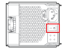
3 Turn off the node PCM switches at the back of the controller nodes. (Diagram borrowed from HP 3PAR StoreServ 7000 and 7000c Storage Service Guide)
4 Turn off the node PCM switches at the back of the disk shelves

POWER ON

3PAR will automatically turn its self back on when power is detected so you will just need turn the PCM switches back on.  The order is the reverse of power off:
1 Turn on the node PCM switches at the back of the disk shelves
2 Turn on the node PCM switches at the back of the controller nodes

It would of course be sensible to do a checkhealth after power up to check everything looked OK. If you found this useful you will be interested to see our selection of the best 3PAR posts selected from the 150 posts written on the topic within this blog.

Thursday, January 5, 2017

How to check Fibre Channel HBAs in Linux

Fibre Channel (FC) Host Bus Adapters(HBA) are interface cards that connects the host system to a fibre channel network or devices. The two major manufacturers of FC HBAs are QLogic and Emulex and the drivers for many HBAs are distributed in-box with the Operating Systems. If the drivers are not available on your Linux version, you need to install them manually and load the modules in kernel
Here is a step by step guide to verify that your FC HBAs installed and configured correctly.

Step-1: Determine the Manufacturer and Model of the HBAs.

Run the lspci command to list all PCI cards detected on the system.
# lspci | grep "Fibre Channel"
07:00.0 Fibre Channel: QLogic Corp. ISP2532-based 8Gb Fibre Channel to PCI Express HBA (rev 02)
0a:00.0 Fibre Channel: QLogic Corp. ISP2532-based 8Gb Fibre Channel to PCI Express HBA (rev 02)
The above output shows the system bus has detected two QLogic HBAs.

Step-2: Get the Vendor and Device IDs for the HBAs installed.

These can be obtained from the file /usr/share/hwdata/pci.ids
# vi /usr/share/hwdata/pci.ids
.....
1077  QLogic Corp.
 2532  ISP2532-based 8Gb Fibre Channel to PCI Express HBA
.....
The vendor id for QLogic is 1077 and the device id is 2532. You could confirm this using the lspci -nn command as shown below
# lspci -nn | grep "Fibre Channel"
07:00.0 Fibre Channel [0c04]: QLogic Corp. ISP2532-based 8Gb Fibre Channel to PCI Express HBA [1077:2532] (rev 02)
0a:00.0 Fibre Channel [0c04]: QLogic Corp. ISP2532-based 8Gb Fibre Channel to PCI Express HBA [1077:2532] (rev 02)

Step-3: Check if the driver modules are installed.

This can be done by searching the list of available modules. (Replace 2.6.18-308.el5PAE with your kernel version in the command below)
# grep 1077 /lib/modules/2.6.18-308.el5PAE/modules.* | grep 2532
/lib/modules/2.6.18-308.el5PAE/modules.alias:alias pci:v00001077d00002532sv*sd*bc*sc*i* qla2xxx
/lib/modules/2.6.18-308.el5PAE/modules.pcimap:qla2xxx              0x00001077 0x00002532 0xffffffff 0xffffffff 0x00000000 0x00000000 0x0
The above output shows that this HBA is supported by the module qla2xxx

Step-4: Check if the drivers for these HBAs are loaded in the kernel.

The lsmod command will list the currently loaded kernel modules
# lsmod | grep qla2xxx
qla2xxx              1205905  0
scsi_transport_fc      44745  1 qla2xxx
scsi_mod              144277  16 be2iscsi, ib_iser, iscsi_tcp, bnx2i, libcxgbi, libiscsi2, scsi_transport_iscsi2, scsi_dh, sr_mod, sg, usb_storage, qla2xxx, scsi_transport_fc, libata,cciss, sd_mod
The output shows the module qla2xxx is loaded by the kernel. If you don't see any output for lsmod command then you can load the module using modprobe command
# modprobe -v qla2xxx

Step-5: Getting detailed information

You can find detailed information about the fibre channel adapters in the location /sys/class/fc_host/
# ll /sys/class/fc_host/
drwxr-xr-x 3 root root 0 Feb  5 11:28 host3
drwxr-xr-x 3 root root 0 Feb  5 11:28 host4
The directories host3 and host4 in the example above contains information specific to each adapter like node name (WWN), port name (WWN), type, speed,state etc.,
An easier way to get this information is to use the systool command.
# systool -c fc_host
Class = "fc_host"
  Class Device = "host3"
    Device = "host3"
  Class Device = "host4"
    Device = "host4"
The -v option gives you detailed output
# systool -c fc_host -v host3
Class = "fc_host"

 Class Device = "host3"
 Class Device path = "/sys/class/fc_host/host3"
   fabric_name         = "0x50014380272531e9"
   issue_lip           = 
   node_name           = "0x50014380281412e9"
   port_id             = "0x0000e8"
   port_name           = "0x50014380281412e8"
   port_state          = "Online"
   port_type           = "LPort (private loop)"
   speed               = "8 Gbit"
   supported_classes   = "Class 3"
   supported_speeds    = "1 Gbit, 2 Gbit, 4 Gbit, 8 Gbit"
   symbolic_name       = "HPAK344A FW:v5.06.03 DVR:v8.03.07.09.05.08-k"
   system_hostname     = ""
   tgtid_bind_type     = "wwpn (World Wide Port Name)"
   uevent              = 

   Device = "host3"
   Device path = "/sys/devices/pci0000:00/0000:00:01.0/0000:07:00.0/host3"
     edc               = 
     fw_dump           =
     nvram             = "ISP "
     optrom_ctl        = 
     optrom            =
     reset             = 
     sfp               = ""
     uevent            = 
     vpd               = "&"

Tuesday, September 6, 2016

Mac OS X - Adding a Networked Print Queue (SMB)


Original link: https://it.faa.illinois.edu/services/printing/57-printing-services/220-add-printer-mac-smb

Overview

These directions explain how to add a networked printer on Mac OS X via the SMB protocol. This is typically used for:
AD-bound Macs may occasionally connect to a Windows server via SMB as well.

Systems

Users

  • All users of above systems

Actions

  1. Gather the following information for the networked printer: server URL, queue name, printer location, and printer model information/features. This information may be available on the printing documentation page for your department. If you cannot locate any of this information, please create an Technology Services at FAA Help Desk help request.
  2. (If necessary) Download and install the appropriate driver for the printer. If your Mac is Fully Managed or Semi-Managed, the driver may already be installed. Please create an Technology Services at FAA Help Desk help request if you need assistance.
  3. Open System Preferences.app. 3-system preferences
  4. Click on "Print & Scan" and unlock the preference pane (if necessary). 4-print and scan
  5. Click on "+" underneath the list of printers and select "Add Printer or Scanner..." in the menu that appears. 5-add printer scanner
  6. An "Add" window will appear. If there is not already an "Advanced" button in its toolbar (on top, alongside "Default", "Fax", "IP", etc.), you'll need to customize the toolbar. Control+click on the toolbar area and select "Customize Toolbar...". 6-smb-customize-toolbar
  7. Drag the "Advanced" item up onto the toolbar and click "Done". 7-smb-drag-advanced
  8. Click on the "Advanced" button. 8-smb-click-on-advanced
  9. Then enter/select the following:
    • Type: "Windows printer via spoolss"
    • Device: "Another Device"
    • URL: smb:///
    • Name: enter a descriptive name here (suggestion: include the queue name so that Technology Services at FAA can help troubleshoot later, if necessary)
    • Location: enter the location for your reference
    • Use: Generally select "Select Printer Software...", locate the appropriate driver for the printer, and click "OK".
    (Reminder: Address, Queue, Location, and installed options for the printer may be available on the printing documentation page for your department. If you cannot locate any of this information, please create an Technology Services at FAA Help Desk help request.)
    9-smb-enter-info
  10. Click "Add". 10-smb-click-add
  11. Configure the appropriate installed options for the printer, then click "OK". 11-smb-options
  12. The first time you print, you will generally be prompted to authenticate with your Active Directory (AD) credentials. Please enter uofi\ and your Active Directory password. You may save your credentials in your Keychain by first checking the appropriate box in the authentication window. osx_smb_print_auth

Saturday, July 30, 2016

Set Up The VPN Server and Client on Mac OSX Server

OS X Server has long had a VPN service that can be run. The server is capable of running the two most commonly used VPN protocols: PPTP and L2TP. The L2TP protocol is always in use, but the server can run both concurrently. You should use L2TP when at all possible.
Sure, “All the great themes have been used up and turned into theme parks.” But security is a theme that it never hurts to keep in the forefront of your mind. If you were thinking of exposing the other services in Yosemite Server to the Internet without having users connect to a VPN service then you should think again, because the VPN service is simple to setup and even simpler to manage.

Setting Up The VPN Service In Yosemite Server

To setup the VPN service, open the Server app and click on VPN in the Server app sidebar. The VPN Settings  screen has two options available in the “Configure VPN for” field, which has two options:
  • L2TP: Enables only the L2TP protocol
  • L2TP and PPTP: Enables both the L2TP protocol and the PPTP protocol
vpn1

The VPN Host Name field is used by administrators leveraging profiles. The setting used becomes the address for the VPN service in the Everyone profile. L2TP requires a shared secret or an SSL certificate. In this example, we’ll configure a shared secret by providing a password in the Shared Secret field. Additionally, there are three fields, each with an Edit button that allows for configuration:
  • Client Addresses: The dynamic pool of addresses provided when clients connect to the VPN

    vpn2


  • DNS Settings: The name servers used once a VPN client has connected to the server. As well as the Search Domains configuration.

    vpn3
  • Routes: Select which interface (VPN or default interface of the client system) that a client connects to each IP address and subnet mask over.
  • vpn4


  • Save Configuration Profile: Use this button to export configuration profiles to a file, which can then be distributed to client systems (OS X using the profiles command, iOS using Apple Configurator or both using Profile Manager).
Once configured, open incoming ports on the router/firewall. PPTP runs over port 1723. L2TP is a bit more complicated (with keys bigger than a baby’s arm), running over 1701, but also the IP-ESP protocol (IP Protocol 50). Both are configured automatically when using Apple AirPorts as gateway devices. Officially, the ports to forward are listed at http://support.apple.com/kb/TS1629.

Using The Command Line

I know, I’ve described ways to manage these services from the command line before. But, “tonight we have number twelve of one hundred things to do with your body when you’re all alone.” The serveradmin command can be used to manage the service as well as the Server app. The serveradmin command can start the service, using the default settings, with no further configuration being required:

sudo serveradmin start vpn

And to stop the service:

sudo serveradmin stop vpn

And to list the available options:

sudo serveradmin settings vpn

The output of which shows all of the VPN settings available via serveradmin (which is many more than what you see in the Server app:

vpn:vpnHost = "mavserver.krypted.lan"
vpn:Servers:com.apple.ppp.pptp:Server:Logfile = "/var/log/ppp/vpnd.log"
vpn:Servers:com.apple.ppp.pptp:Server:VerboseLogging = 1
vpn:Servers:com.apple.ppp.pptp:Server:MaximumSessions = 128
vpn:Servers:com.apple.ppp.pptp:DNS:OfferedSearchDomains = _empty_array
vpn:Servers:com.apple.ppp.pptp:DNS:OfferedServerAddresses = _empty_array
vpn:Servers:com.apple.ppp.pptp:Radius:Servers:_array_index:0:SharedSecret = "1"
vpn:Servers:com.apple.ppp.pptp:Radius:Servers:_array_index:0:Address = "1.1.1.1"
vpn:Servers:com.apple.ppp.pptp:Radius:Servers:_array_index:1:SharedSecret = "2"
vpn:Servers:com.apple.ppp.pptp:Radius:Servers:_array_index:1:Address = "2.2.2.2"
vpn:Servers:com.apple.ppp.pptp:enabled = yes
vpn:Servers:com.apple.ppp.pptp:Interface:SubType = "PPTP"
vpn:Servers:com.apple.ppp.pptp:Interface:Type = "PPP"
vpn:Servers:com.apple.ppp.pptp:PPP:LCPEchoFailure = 5
vpn:Servers:com.apple.ppp.pptp:PPP:DisconnectOnIdle = 1
vpn:Servers:com.apple.ppp.pptp:PPP:AuthenticatorEAPPlugins:_array_index:0 = "EAP-RSA"
vpn:Servers:com.apple.ppp.pptp:PPP:AuthenticatorACLPlugins:_array_index:0 = "DSACL"
vpn:Servers:com.apple.ppp.pptp:PPP:CCPEnabled = 1
vpn:Servers:com.apple.ppp.pptp:PPP:IPCPCompressionVJ = 0
vpn:Servers:com.apple.ppp.pptp:PPP:ACSPEnabled = 1
vpn:Servers:com.apple.ppp.pptp:PPP:LCPEchoEnabled = 1
vpn:Servers:com.apple.ppp.pptp:PPP:LCPEchoInterval = 60
vpn:Servers:com.apple.ppp.pptp:PPP:MPPEKeySize128 = 1
vpn:Servers:com.apple.ppp.pptp:PPP:AuthenticatorProtocol:_array_index:0 = "MSCHAP2"
vpn:Servers:com.apple.ppp.pptp:PPP:MPPEKeySize40 = 0
vpn:Servers:com.apple.ppp.pptp:PPP:AuthenticatorPlugins:_array_index:0 = "DSAuth"
vpn:Servers:com.apple.ppp.pptp:PPP:Logfile = "/var/log/ppp/vpnd.log"
vpn:Servers:com.apple.ppp.pptp:PPP:VerboseLogging = 1
vpn:Servers:com.apple.ppp.pptp:PPP:DisconnectOnIdleTimer = 7200
vpn:Servers:com.apple.ppp.pptp:PPP:CCPProtocols:_array_index:0 = "MPPE"
vpn:Servers:com.apple.ppp.pptp:IPv4:ConfigMethod = "Manual"
vpn:Servers:com.apple.ppp.pptp:IPv4:DestAddressRanges:_array_index:0 = "192.168.210.240"
vpn:Servers:com.apple.ppp.pptp:IPv4:DestAddressRanges:_array_index:1 = "192.168.210.254"
vpn:Servers:com.apple.ppp.pptp:IPv4:OfferedRouteAddresses = _empty_array
vpn:Servers:com.apple.ppp.pptp:IPv4:OfferedRouteTypes = _empty_array
vpn:Servers:com.apple.ppp.pptp:IPv4:OfferedRouteMasks = _empty_array
vpn:Servers:com.apple.ppp.l2tp:Server:LoadBalancingAddress = "1.2.3.4"
vpn:Servers:com.apple.ppp.l2tp:Server:MaximumSessions = 128
vpn:Servers:com.apple.ppp.l2tp:Server:LoadBalancingEnabled = 0
vpn:Servers:com.apple.ppp.l2tp:Server:Logfile = "/var/log/ppp/vpnd.log"
vpn:Servers:com.apple.ppp.l2tp:Server:VerboseLogging = 1
vpn:Servers:com.apple.ppp.l2tp:DNS:OfferedSearchDomains = _empty_array
vpn:Servers:com.apple.ppp.l2tp:DNS:OfferedServerAddresses = _empty_array
vpn:Servers:com.apple.ppp.l2tp:Radius:Servers:_array_index:0:SharedSecret = "1"
vpn:Servers:com.apple.ppp.l2tp:Radius:Servers:_array_index:0:Address = "1.1.1.1"
vpn:Servers:com.apple.ppp.l2tp:Radius:Servers:_array_index:1:SharedSecret = "2"
vpn:Servers:com.apple.ppp.l2tp:Radius:Servers:_array_index:1:Address = "2.2.2.2"
vpn:Servers:com.apple.ppp.l2tp:enabled = yes
vpn:Servers:com.apple.ppp.l2tp:Interface:SubType = "L2TP"
vpn:Servers:com.apple.ppp.l2tp:Interface:Type = "PPP"
vpn:Servers:com.apple.ppp.l2tp:PPP:LCPEchoFailure = 5
vpn:Servers:com.apple.ppp.l2tp:PPP:DisconnectOnIdle = 1
vpn:Servers:com.apple.ppp.l2tp:PPP:AuthenticatorEAPPlugins:_array_index:0 = "EAP-KRB"
vpn:Servers:com.apple.ppp.l2tp:PPP:AuthenticatorACLPlugins:_array_index:0 = "DSACL"
vpn:Servers:com.apple.ppp.l2tp:PPP:VerboseLogging = 1
vpn:Servers:com.apple.ppp.l2tp:PPP:IPCPCompressionVJ = 0
vpn:Servers:com.apple.ppp.l2tp:PPP:ACSPEnabled = 1
vpn:Servers:com.apple.ppp.l2tp:PPP:LCPEchoInterval = 60
vpn:Servers:com.apple.ppp.l2tp:PPP:LCPEchoEnabled = 1
vpn:Servers:com.apple.ppp.l2tp:PPP:AuthenticatorProtocol:_array_index:0 = "MSCHAP2"
vpn:Servers:com.apple.ppp.l2tp:PPP:AuthenticatorPlugins:_array_index:0 = "DSAuth"
vpn:Servers:com.apple.ppp.l2tp:PPP:Logfile = "/var/log/ppp/vpnd.log"
vpn:Servers:com.apple.ppp.l2tp:PPP:DisconnectOnIdleTimer = 7200
vpn:Servers:com.apple.ppp.l2tp:IPSec:SharedSecretEncryption = "Keychain"
vpn:Servers:com.apple.ppp.l2tp:IPSec:LocalIdentifier = ""
vpn:Servers:com.apple.ppp.l2tp:IPSec:SharedSecret = "com.apple.ppp.l2tp"
vpn:Servers:com.apple.ppp.l2tp:IPSec:AuthenticationMethod = "SharedSecret"
vpn:Servers:com.apple.ppp.l2tp:IPSec:RemoteIdentifier = ""
vpn:Servers:com.apple.ppp.l2tp:IPSec:IdentifierVerification = "None"
vpn:Servers:com.apple.ppp.l2tp:IPSec:LocalCertificate = <>
vpn:Servers:com.apple.ppp.l2tp:IPv4:ConfigMethod = "Manual"
vpn:Servers:com.apple.ppp.l2tp:IPv4:DestAddressRanges:_array_index:0 = "192.168.210.224"
vpn:Servers:com.apple.ppp.l2tp:IPv4:DestAddressRanges:_array_index:1 = "192.168.210.239"
vpn:Servers:com.apple.ppp.l2tp:IPv4:OfferedRouteAddresses = _empty_array
vpn:Servers:com.apple.ppp.l2tp:IPv4:OfferedRouteTypes = _empty_array
vpn:Servers:com.apple.ppp.l2tp:IPv4:OfferedRouteMasks = _empty_array
vpn:Servers:com.apple.ppp.l2tp:L2TP:Transport = "IPSec"
vpn:Servers:com.apple.ppp.l2tp:L2TP:IPSecSharedSecretValue = "yaright"

To disable L2TP, set vpn:Servers:com.apple.ppp.l2tp:enabled to no:

sudo serveradmin settings vpn:Servers:com.apple.ppp.l2tp:enabled = no

To configure how long a client can be idle prior to being disconnected:

sudo serveradmin settings vpn:Servers:com.apple.ppp.l2tp:PPP:DisconnectOnIdle = 10

By default, each protocol has a maximum of 128 sessions, configureable using vpn:Servers:com.apple.ppp.pptp:Server:MaximumSessions:

sudo serveradmin settings vpn:Servers:com.apple.ppp.pptp:Server:MaximumSessions = 200

To see the state of the service, the pid, the time the service was configured, the path to the log files,
the number of clients and other information, use the fullstatus option:

sudo serveradmin fullstatus vpn

Which returns output similar to the following:

vpn:servicePortsAreRestricted = "NO"
vpn:readWriteSettingsVersion = 1
vpn:servers:com.apple.ppp.pptp:AuthenticationProtocol = "MSCHAP2"
vpn:servers:com.apple.ppp.pptp:CurrentConnections = 0
vpn:servers:com.apple.ppp.pptp:enabled = yes
vpn:servers:com.apple.ppp.pptp:MPPEKeySize = "MPPEKeySize128"
vpn:servers:com.apple.ppp.pptp:Type = "PPP"
vpn:servers:com.apple.ppp.pptp:SubType = "PPTP"
vpn:servers:com.apple.ppp.pptp:AuthenticatorPlugins = "DSAuth"
vpn:servers:com.apple.ppp.l2tp:AuthenticationProtocol = "MSCHAP2"
vpn:servers:com.apple.ppp.l2tp:Type = "PPP"
vpn:servers:com.apple.ppp.l2tp:enabled = yes
vpn:servers:com.apple.ppp.l2tp:CurrentConnections = 0
vpn:servers:com.apple.ppp.l2tp:SubType = "L2TP"
vpn:servers:com.apple.ppp.l2tp:AuthenticatorPlugins = "DSAuth"
vpn:servicePortsRestrictionInfo = _empty_array
vpn:health = _empty_dictionary
vpn:logPaths:vpnLog = "/var/log/ppp/vpnd.log"
vpn:configured = yes
vpn:state = "STOPPED"
vpn:setStateVersion = 1

Security folk will be stoked to see that the shared secret is shown in the clear using:

vpn:Servers:com.apple.ppp.l2tp:L2TP:IPSecSharedSecretValue = "a dirty thought in a nice clean mind"

Configuring Users For VPN Access

Each account that accesses the VPN server needs a valid account to do so. To configure existing users to use the service, click on Users in the Server app sidebar.

vpn5

At the list of users, click on a user and then click on the cog wheel icon, selecting Edit Access to Services.

vpn6

At the Service Access screen will be a list of services that could be hosted on the server; verify the checkbox for VPN is highlighted for the user. If not, click Manage Service Access, click Manage and then check the VPN box.

vpn7

Setting Up Client Computers

As you can see, configuring the VPN service in Yosemite Server (OS X Server 2.2) is a simple and straight-forward process – much easier than eating your cereal with a fork and doing your homework in the dark.. Configuring clients is as simple as importing the profile generated by the service. However, you can also configure clients manually. To do so in OS X, open the Network System Preference pane. From here, click on the plus sign (“+”) to add a new network service.

vpn8

At the prompt, select VPN in the Interface field and then either PPTP or L2TP over IPSec in the VPN Type. Then provide a name for the connection in the Service Name field and click on Create.

vpn9

At the list of network interfaces in the Network System Preference pane, provide the hostname or address of the server in the Server Address field and the username that will be connecting to the VPN service in the Account Name field. If using L2TP, click on Authentication Settings.

vpn10
At the prompt, provide the password entered into the Shared Secret field earlier in this article in the Machine Authentication Shared Secret field and the user’s password in the User Authentication Password field. When you’re done, click OK and then provided you’re outside the network and routeable to the server, click on Connect to test the connection.

Conclusion

Setting Up the VPN service in OS X Yosemite Server is as simple as clicking the ON button. But much more information about using a VPN can be required. The natd binary is still built into Yosemite at /usr/sbin/natd and can be managed in a number of ways. But it’s likely that the days of using an OS X Server as a gateway device are over, if they ever started. Sure “feeling screwed up at a screwed up time in a screwed up place does not necessarily make you screwed up” but using an OS X Server for NAT when it isn’t even supported any more probably does. So rather than try to use the server as both, use a 3rd party firewall like most everyone else and then use the server as a VPN appliance. Hopefully it can do much more than just that to help justify the cost. And if you’re using an Apple AirPort as a router (hopefully in a very small environment) then the whole process of setting this thing up should be super-simple.

Friday, July 15, 2016

Network Recommendations for a Hyper-V Cluster in Windows Server 2012

Technet article: https://technet.microsoft.com/en-us/library/dn550728%28v=ws.11%29.aspx?f=255&MSPPError=-2147217396 
Applies To: Windows Server 2012
There are several different types of network traffic that you must consider and plan for when you deploy a highly available Hyper-V solution. You should design your network configuration with the following goals in mind:
  • To ensure network quality of service
  • To provide network redundancy
  • To isolate traffic to defined networks
  • Where applicable, take advantage of Server Message Block (SMB) Multichannel
This topic provides network configuration recommendations that are specific to a Hyper-V cluster that is running Windows Server 2012. It includes an overview of the different network traffic types, recommendations for how to isolate traffic, recommendations for features such as NIC Teaming, Quality of Service (QoS) and Virtual Machine Queue (VMQ), and a Windows PowerShell script that shows an example of converged networking, where the network traffic on a Hyper-V cluster is routed through one external virtual switch.
Windows Server 2012 supports the concept of converged networking, where different types of network traffic share the same Ethernet network infrastructure. In previous versions of Windows Server, the typical recommendation for a failover cluster was to dedicate separate physical network adapters to different traffic types. Improvements in Windows Server 2012, such as Hyper-V QoS and the ability to add virtual network adapters to the management operating system enable you to consolidate the network traffic on fewer physical adapters. Combined with traffic isolation methods such as VLANs, you can isolate and control the network traffic.
System_CAPS_importantImportant
If you use System Center Virtual Machine Manager (VMM) to create or manage Hyper-V clusters, you must use VMM to configure the network settings that are described in this topic.
In this topic:

When you deploy a Hyper-V cluster, you must plan for several types of network traffic. The following table summarizes the different traffic types.
Network Traffic TypeDescription
Management
  • Provides connectivity between the server that is running Hyper-V and basic infrastructure functionality.
  • Used to manage the Hyper-V management operating system and virtual machines.
Cluster
  • Used for inter-node cluster communication such as the cluster heartbeat and Cluster Shared Volumes (CSV) redirection.
Live migration
  • Used for virtual machine live migration.
Storage
  • Used for SMB traffic or for iSCSI traffic.
Replica traffic
  • Used for virtual machine replication through the Hyper-V Replica feature.
Virtual machine access
  • Used for virtual machine connectivity.
  • Typically requires external network connectivity to service client requests.
The following sections provide more detailed information about each network traffic type.

A management network provides connectivity between the operating system of the physical Hyper-V host (also known as the management operating system) and basic infrastructure functionality such as Active Directory Domain Services (AD DS), Domain Name System (DNS), and Windows Server Update Services (WSUS). It is also used for management of the server that is running Hyper-V and the virtual machines.
The management network must have connectivity between all required infrastructure, and to any location from which you want to manage the server.

A failover cluster monitors and communicates the cluster state between all members of the cluster. This communication is very important to maintain cluster health. If a cluster node does not communicate a regular health check (known as the cluster heartbeat), the cluster considers the node down and removes the node from cluster membership. The cluster then transfers the workload to another cluster node.
Inter-node cluster communication also includes traffic that is associated with CSV. For CSV, where all nodes of a cluster can access shared block-level storage simultaneously, the nodes in the cluster must communicate to orchestrate storage-related activities. Also, if a cluster node loses its direct connection to the underlying CSV storage, CSV has resiliency features which redirect the storage I/O over the network to another cluster node that can access the storage.

Live migration enables the transparent movement of running virtual machines from one Hyper-V host to another without a dropped network connection or perceived downtime.
We recommend that you use a dedicated network or VLAN for live migration traffic to ensure quality of service and for traffic isolation and security. Live migration traffic can saturate network links. This can cause other traffic to experience increased latency. The time it takes to fully migrate one or more virtual machines depends on the throughput of the live migration network. Therefore, you must ensure that you configure the appropriate quality of service for this traffic. To provide the best performance, live migration traffic is not encrypted.
You can designate multiple networks as live migration networks in a prioritized list. For example, you may have one migration network for cluster nodes in the same cluster that is fast (10 GB), and a second migration network for cross-cluster migrations that is slower (1 GB).
All Hyper-V hosts that can initiate or receive a live migration must have connectivity to a network that is configured to allow live migrations. Because live migration can occur between nodes in the same cluster, between nodes in different clusters, and between a cluster and a stand-alone Hyper-V host, make sure that all these servers can access a live migration-enabled network.

For a virtual machine to be highly available, all members of the Hyper-V cluster must be able to access the virtual machine state. This includes the configuration state and the virtual hard disks. To meet this requirement, you must have shared storage.
In Windows Server 2012, there are two ways that you can provide shared storage:
  • Shared block storage. Shared block storage options include Fibre Channel, Fibre Channel over Ethernet (FCoE), iSCSI, and shared Serial Attached SCSI (SAS).
  • File-based storage. Remote file-based storage is provided through SMB 3.0.
SMB 3.0 includes new functionality known as SMB Multichannel. SMB Multichannel automatically detects and uses multiple network interfaces to deliver high performance and highly reliable storage connectivity.
By default, SMB Multichannel is enabled, and requires no additional configuration. You should use at least two network adapters of the same type and speed so that SMB Multichannel is in effect. Network adapters that support RDMA (Remote Direct Memory Access) are recommended but not required.
SMB 3.0 also automatically discovers and takes advantage of available hardware offloads, such as RDMA. A feature known as SMB Direct supports the use of network adapters that have RDMA capability. SMB Direct provides the best performance possible while also reducing file server and client overhead.
System_CAPS_noteNote
The NIC Teaming feature is incompatible with RDMA-capable network adapters. Therefore, if you intend to use the RDMA capabilities of the network adapter, do not team those adapters.
Both iSCSI and SMB use the network to connect the storage to cluster members. Because reliable storage connectivity and performance is very important for Hyper-V virtual machines, we recommend that you use multiple networks (physical or logical) to ensure that these requirements are achieved.

Hyper-V Replica provides asynchronous replication of Hyper-V virtual machines between two hosting servers or Hyper-V clusters. Replica traffic occurs between the primary and Replica sites.
Hyper-V Replica automatically discovers and uses available network interfaces to transmit replication traffic. To throttle and control the replica traffic bandwidth, you can define QoS policies with minimum bandwidth weight.
If you use certificate-based authentication, Hyper-V Replica encrypts the traffic. If you use Kerberos-based authentication, traffic is not encrypted.

Most virtual machines require some form of network or Internet connectivity. For example, workloads that are running on virtual machines typically require external network connectivity to service client requests. This can include tenant access in a hosted cloud implementation. Because multiple subclasses of traffic may exist, such as traffic that is internal to the datacenter and traffic that is external (for example to a computer outside the datacenter or to the Internet); one or more networks are required for these virtual machines to communicate.
To separate virtual machine traffic from the management operating system, we recommend that you use VLANs which are not exposed to the management operating system.

To provide the most consistent performance and functionality, and to improve network security, we recommend that you isolate the different types of network traffic.
System_CAPS_noteNote
Realize that if you want to have a physical or logical network that is dedicated to a specific traffic type, you must assign each physical or virtual network adapter to a unique subnet. For each cluster node, Failover Clustering recognizes only one IP address per subnet.

We recommend that you use a firewall or IPsec encryption, or both, to isolate management traffic. In addition, you can use auditing to ensure that only defined and allowed communication is transmitted through the management network.

To isolate inter-node cluster traffic, you can configure a network to either allow cluster network communication or not to allow cluster network communication. For a network that allows cluster network communication, you can also configure whether to allow clients to connect through the network. (This includes client and management operating system access.)
A failover cluster can use any network that allows cluster network communication for cluster monitoring, state communication, and for CSV-related communication.
To configure a network to allow or not to allow cluster network communication, you can use Failover Cluster Manager or Windows PowerShell. To use Failover Cluster Manager, click Networks in the navigation tree. In the Networks pane, right-click a network, and then click Properties.
Failover Cluster Manager network properties
Figure 1. Failover Cluster Manager network properties
The following Windows PowerShell example configures a network named Management Network to allow cluster and client connectivity.
(Get-ClusterNetwork -Name "Management Network").Role = 3

The Role property has the following possible values.
ValueNetwork Setting
0Do not allow cluster network communication
1Allow cluster network communication only
3Allow cluster network communication and client connectivity
The following table shows the recommended settings for each type of network traffic. Realize that virtual machine access traffic is not listed because these networks should be isolated from the management operating system by using VLANs that are not exposed to the host. Therefore, virtual machine networks should not appear in Failover Cluster Manager as cluster networks.
Network TypeRecommended Setting
ManagementBoth of the following:
  • Allow cluster network communication on this network
  • Allow clients to connect through this network
ClusterAllow cluster network communication on this network
System_CAPS_noteNote
Clear the Allow clients to connect through this network check box.
Live migrationAllow cluster network communication on this network
System_CAPS_noteNote
Clear the Allow clients to connect through this network check box.
StorageDo not allow cluster network communication on this network
Replica trafficBoth of the following:
  • Allow cluster network communication on this network
  • Allow clients to connect through this network

By default, live migration traffic uses the cluster network topology to discover available networks and to establish priority. However, you can manually configure live migration preferences to isolate live migration traffic to only the networks that you define. To do this, you can use Failover Cluster Manager or Windows PowerShell. To use Failover Cluster Manager, in the navigation tree, right-click Networks, and then click Live Migration Settings.
Screenshot of Live Migration Settings dialog box
Figure 2. Live migration settings in Failover Cluster Manager
The following Windows PowerShell example enables live migration traffic only on a network that is named Migration_Network.
Get-ClusterResourceType -Name "Virtual Machine" | Set-ClusterParameter -Name MigrationExcludeNetworks -Value ([String]::Join(";",(Get-ClusterNetwork | Where-Object {$_.Name -ne "Migration_Network"}).ID)) 

To isolate SMB storage traffic, you can use Windows PowerShell to set SMB Multichannel constraints. SMB Multichannel constraints restrict SMB communication between a given file server and the Hyper-V host to one or more defined network interfaces.
For example, the following Windows PowerShell command sets a constraint for SMB traffic from the file server FileServer1 to the network interfaces SMB1, SMB2, SMB3, and SMB4 on the Hyper-V host from which you run this command.
New-SmbMultichannelConstraint -ServerName "FileServer1" -InterfaceAlias "SMB1", "SMB2", "SMB3", "SMB4"

System_CAPS_noteNote
  • You must run this command on each node of the Hyper-V cluster.
  • To find the interface name, use the Get-NetAdapter cmdlet.
For more information, see New-SmbMultichannelConstraint.
To isolate iSCSI traffic, configure the iSCSI target with interfaces on a dedicated network (logical or physical). Use the corresponding interfaces on the cluster nodes when you configure the iSCSI initiator.

To isolate Hyper-V Replica traffic, we recommend that you use a different subnet for the primary and Replica sites.
If you want to isolate the replica traffic to a particular network adapter, you can define a persistent static route which redirects the network traffic to the defined network adapter. To specify a static route, use the following command:
route add mask if -p
For example, to add a static route to the 10.1.17.0 network (example network of the Replica site) that uses a subnet mask of 255.255.255.0, a gateway of 10.0.17.1 (example IP address of the primary site), where the interface number for the adapter that you want to dedicate to replica traffic is 8, run the following command:
route add 10.1.17.1 mask 255.255.255.0 10.0.17.1 if 8 -p

We recommend that you team physical network adapters in the management operating system. This provides bandwidth aggregation and network traffic failover if a network hardware failure or outage occurs.
The NIC Teaming feature, also known as load balancing and failover (LBFO), provides two basic sets of algorithms for teaming.
  • Switch-dependent modes. Requires the switch to participate in the teaming process. Typically requires all the network adapters in the team to be connected to the same switch.
  • Switch-independent modes. Does not require the switch to participate in the teaming process. Although not required, team network adapters can be connected to different switches.
Both modes provide for bandwidth aggregation and traffic failover if a network adapter failure or network disconnection occurs. However, in most cases only switch-independent teaming provides traffic failover for a switch failure.
NIC Teaming also provides a traffic distribution algorithm that is optimized for Hyper-V workloads. This algorithm is referred to as the Hyper-V port load balancing mode. This mode distributes the traffic based on the MAC address of the virtual network adapters. The algorithm uses round robin as the load-balancing mechanism. For example, on a server that has two teamed physical network adapters and four virtual network adapters, the first and third virtual network adapter will use the first physical adapter, and the second and fourth virtual network adapter will use the second physical adapter. Hyper-V port mode also enables the use of hardware offloads such as virtual machine queue (VMQ) which reduces CPU overhead for networking operations.
Recommendations
For a clustered Hyper-V deployment, we recommend that you use the following settings when you configure the additional properties of a team.
Property NameRecommended Setting
Teaming modeSwitch Independent (the default setting)
Load balancing modeHyper-V Port
System_CAPS_noteNote
NIC teaming will effectively disable the RDMA capability of the network adapters. If you want to use SMB Direct and the RDMA capability of the network adapters, you should not use NIC Teaming.
For more information about the NIC Teaming modes and how to configure NIC Teaming settings, see Windows Server 2012 NIC Teaming (LBFO) Deployment and Management and NIC Teaming Overview.

You can use QoS technologies that are available in Windows Server 2012 to meet the service requirements of a workload or an application. QoS provides the following:
  • Measures network bandwidth, detects changing network conditions (such as congestion or availability of bandwidth), and prioritizes - or throttles - network traffic.
  • Enables you to converge multiple types of network traffic on a single adapter.
  • Includes a minimum bandwidth feature which guarantees a certain amount of bandwidth to a given type of traffic.
We recommend that you configure appropriate Hyper-V QoS on the virtual switch to ensure that network requirements are met for all appropriate types of network traffic on the Hyper-V cluster.
System_CAPS_noteNote
You can use QoS to control outbound traffic, but not the inbound traffic. For example, with Hyper-V Replica, you can use QoS to control outbound traffic (from the primary server), but not the inbound traffic (from the Replica server).
Recommendations
For a Hyper-V cluster, we recommend that you configure Hyper-V QoS that applies to the virtual switch. When you configure QoS, do the following:
  • Configure minimum bandwidth in weight mode instead of in bits per second. Minimum bandwidth specified by weight is more flexible and it is compatible with other features, such as live migration and NIC Teaming. For more information, see the MinimumBandwidthMode parameter in New-VMSwitch.
  • Enable and configure QoS for all virtual network adapters. Assign a weight to all virtual adapters. For more information, see Set-VMNetworkAdapter. To make sure that all virtual adapters have a weight, configure the DefaultFlowMinimumBandwidthWeight parameter on the virtual switch to a reasonable value. For more information, see Set-VMSwitch.
The following table recommends some generic weight values. You can assign a value from 1 to 100. For guidelines to consider when you assign weight values, see Guidelines for using Minimum Bandwidth.
Network ClassificationWeight
Default weight0
Virtual machine access1, 3 or 5 (low, medium and high-throughput virtual machines)
Cluster10
Management10
Replica traffic10
Live migration40
Storage40

Virtual machine queue (VMQ) is a feature that is available to computers that have VMQ-capable network hardware. VMQ uses hardware packet filtering to deliver packet data from an external virtual network directly to virtual network adapters. This reduces the overhead of routing packets. When VMQ is enabled, a dedicated queue is established on the physical network adapter for each virtual network adapter that has requested a queue.
Not all physical network adapters support VMQ. Those that do support VMQ will have a fixed number of queues available, and the number will vary. To determine whether a network adapter supports VMQ, and how many queues they support, use the Get-NetAdapterVmq cmdlet.
You can assign virtual machine queues to any virtual network adapter. This includes virtual network adapters that are exposed to the management operating system. Queues are assigned according to a weight value, in a first-come first-serve manner. By default, all virtual adapters have a weight of 100.
Recommendations
We recommend that you increase the VMQ weight for interfaces with heavy inbound traffic, such as storage and live migration networks. To do this, use the Set-VMNetworkAdapter Windows PowerShell cmdlet.

The following Windows PowerShell script shows an example of how you can route traffic on a Hyper-V cluster through one Hyper-V external virtual switch. The example uses two physical 10 GB network adapters that are teamed by using the NIC Teaming feature. The script configures a Hyper-V cluster node with a management interface, a live migration interface, a cluster interface, and four SMB interfaces. After the script, there is more information about how to add an interface for Hyper-V Replica traffic. The following diagram shows the example network configuration.
Diagram of Hyper-V cluster networks
Figure 3. Example Hyper-V cluster network configuration
The example also configures network isolation which restricts cluster traffic from the management interface, restricts SMB traffic to the SMB interfaces, and restricts live migration traffic to the live migration interface.
# Create a network team using switch independent teaming and Hyper-V port mode
New-NetLbfoTeam "PhysicalTeam" –TeamMembers "10GBPort1", "10GBPort2" –TeamNicName "PhysicalTeam" -TeamingMode SwitchIndependent -LoadBalancingAlgorithm HyperVPort

# Create a Hyper-V virtual switch connected to the network team
# Enable QoS in Weight mode
New-VMSwitch "TeamSwitch" –NetAdapterName "PhysicalTeam" –MinimumBandwidthMode Weight –AllowManagementOS $false

# Configure the default bandwidth weight for the switch
# Ensures all virtual NICs have a weight
Set-VMSwitch -Name "TeamSwitch" -DefaultFlowMinimumBandwidthWeight 0

# Create virtual network adapters on the management operating system
# Connect the adapters to the virtual switch
# Set the VLAN associated with the adapter
# Configure the VMQ weight and minimum bandwidth weight
Add-VMNetworkAdapter –ManagementOS –Name "Management" –SwitchName "TeamSwitch"
Set-VMNetworkAdapterVlan -ManagementOS -VMNetworkAdapterName "Management" -Access -VlanId 10
Set-VMNetworkAdapter -ManagementOS -Name "Management" -VmqWeight 80 -MinimumBandwidthWeight 10

Add-VMNetworkAdapter –ManagementOS –Name "Cluster" –SwitchName "TeamSwitch"
Set-VMNetworkAdapterVlan -ManagementOS -VMNetworkAdapterName "Cluster" -Access -VlanId 11
Set-VMNetworkAdapter -ManagementOS -Name "Cluster" -VmqWeight 80 -MinimumBandwidthWeight 10

Add-VMNetworkAdapter –ManagementOS –Name "Migration" –SwitchName "TeamSwitch"
Set-VMNetworkAdapterVlan -ManagementOS -VMNetworkAdapterName "Migration" -Access -VlanId 12
Set-VMNetworkAdapter -ManagementOS -Name "Migration" -VmqWeight 90 -MinimumBandwidthWeight 40

Add-VMNetworkAdapter –ManagementOS –Name "SMB1" –SwitchName "TeamSwitch"
Set-VMNetworkAdapterVlan -ManagementOS -VMNetworkAdapterName "SMB1" -Access -VlanId 13
Set-VMNetworkAdapter -ManagementOS -Name "SMB1" -VmqWeight 100 -MinimumBandwidthWeight 40

Add-VMNetworkAdapter –ManagementOS –Name "SMB2" –SwitchName "TeamSwitch"
Set-VMNetworkAdapterVlan -ManagementOS -VMNetworkAdapterName "SMB2" -Access -VlanId 14
Set-VMNetworkAdapter -ManagementOS -Name "SMB2" -VmqWeight 100 -MinimumBandwidthWeight 40

Add-VMNetworkAdapter –ManagementOS –Name "SMB3" –SwitchName "TeamSwitch"
Set-VMNetworkAdapterVlan -ManagementOS -VMNetworkAdapterName "SMB3" -Access -VlanId 15
Set-VMNetworkAdapter -ManagementOS -Name "SMB3" -VmqWeight 100 -MinimumBandwidthWeight 40

Add-VMNetworkAdapter –ManagementOS –Name "SMB4" –SwitchName "TeamSwitch"
Set-VMNetworkAdapterVlan -ManagementOS -VMNetworkAdapterName "SMB4" -Access -VlanId 16
Set-VMNetworkAdapter -ManagementOS -Name "SMB4" -VmqWeight 100 -MinimumBandwidthWeight 40

# Rename the cluster networks if desired
(Get-ClusterNetwork | Where-Object {$_.Address -eq "10.0.10.0"}).Name = "Management_Network"
(Get-ClusterNetwork | Where-Object {$_.Address -eq "10.0.11.0"}).Name = "Cluster_Network"
(Get-ClusterNetwork | Where-Object {$_.Address -eq "10.0.12.0"}).Name = "Migration_Network"
(Get-ClusterNetwork | Where-Object {$_.Address -eq "10.0.13.0"}).Name = "SMB_Network1"
(Get-ClusterNetwork | Where-Object {$_.Address -eq "10.0.14.0"}).Name = "SMB_Network2"
(Get-ClusterNetwork | Where-Object {$_.Address -eq "10.0.15.0"}).Name = "SMB_Network3"
(Get-ClusterNetwork | Where-Object {$_.Address -eq "10.0.16.0"}).Name = "SMB_Network4"

# Configure the cluster network roles
(Get-ClusterNetwork -Name "Management_Network").Role = 3
(Get-ClusterNetwork -Name "Cluster_Network").Role = 1
(Get-ClusterNetwork -Name "Migration_Network").Role = 1
(Get-ClusterNetwork -Name "SMB_Network1").Role = 0
(Get-ClusterNetwork -Name "SMB_Network2").Role = 0
(Get-ClusterNetwork -Name "SMB_Network3").Role = 0
(Get-ClusterNetwork -Name "SMB_Network4").Role = 0

# Configure an SMB Multichannel constraint
# This ensures that SMB traffic from the named server only uses SMB interfaces
New-SmbMultichannelConstraint -ServerName "FileServer1" -InterfaceAlias "vEthernet (SMB1)", "vEthernet (SMB2)", "vEthernet (SMB3)", "vEthernet (SMB4)"

# Configure the live migration network
Get-ClusterResourceType -Name "Virtual Machine" | Set-ClusterParameter -Name MigrationExcludeNetworks -Value ([String]::Join(";",(Get-ClusterNetwork | Where-Object {$_.Name -ne "Migration_Network"}).ID)) 

Hyper-V Replica considerations
If you also use Hyper-V Replica in your environment, you can add another virtual network adapter to the management operating system for replica traffic. For example:
Add-VMNetworkAdapter –ManagementOS –Name "Replica" –SwitchName "TeamSwitch"
Set-VMNetworkAdapterVlan -ManagementOS -VMNetworkAdapterName "Replica" –Access –VlanId 17
Set-VMNetworkAdapter -ManagementOS -Name "Replica" -VmqWeight 80 -MinimumBandwidthWeight 10

# If the host is clustered – configure the cluster name and role
(Get-ClusterNetwork | Where-Object {$_.Address -eq "10.0.17.0"}).Name = "Replica"
(Get-ClusterNetwork -Name "Replica").Role = 3

System_CAPS_noteNote
If you are instead using policy-based QoS, where you can throttle outgoing traffic regardless of the interface on which it is sent, you can use either of the following methods to throttle Hyper-V Replica traffic:
  • Create a QoS policy that is based on the destination subnet. In this example, the Replica site uses the 10.1.17.0/24 subnet.
    New-NetQosPolicy "Replica traffic to 10.1.17.0" –DestinationAddress 10.1.17.0/24 –MinBandwidthWeightAction 40
    
    
  • Create a QoS policy that is based on the destination port. In the following example, the network listener on the Replica server or cluster has been configured to use port 8080 to receive replication traffic.
    New-NetQosPolicy "Replica traffic to 8080" –DestinationPort 8080 –ThrottleRateActionBitsPerSecond 100000


By default, cluster communication is not encrypted. You can enable encryption if you want. However, realize that there is performance overhead that is associated with encryption. To enable encryption, you can use the following Windows PowerShell command to set the security level for the cluster.
(Get-Cluster). SecurityLevel = 2
The following table shows the different security level values.
Security DescriptionValue
Clear text0
Signed (default)1
Encrypted2

Live migration traffic is not encrypted. You can enable IPsec or other network layer encryption technologies if you want. However, realize that encryption technologies typically affect performance.

By default, SMB traffic is not encrypted. Therefore, we recommend that you use a dedicated network (physical or logical) or use encryption. For SMB traffic, you can use SMB encryption, layer-2 or layer-3 encryption. SMB encryption is the preferred method.

If you use Kerberos-based authentication, Hyper-V Replica traffic is not encrypted. We strongly recommend that you encrypt replication traffic that transits public networks over the WAN or the Internet. We recommend Secure Sockets Layer (SSL) encryption as the encryption method. You can also use IPsec. However, realize that using IPsec may significantly affect performance.

How to use DiskSpd to simulate Veeam Backup & Replication disk actions

This HOW-TO contains information on how to use Microsoft© DiskSpd to simulate Veeam Backup & Replication disk actions to measure disk pe...