It should be simple to configure iSCSI on Windows Server 2012 R2
right? While it is not rocket science and really not that difficult at
all to configure, it’s also not as intuitive as I think it should be.
Therefore I decided to create this post on how to configure iSCSI for a
Windows Server 2012 R2 Hyper-V cluster using an HP MSA 1040 as the
shared storage device.
Equipment
Shared Storage: HP MSA 1040 (4 NICS)
Servers: Quantity of 2 Hyper-V Hosts (each host has 6 NICS)
Network switches: Quantity of 2 network switches (for redundancy)
Operating System: Windows Server 2012 R2
Storage Network: Each Hyper-V host has two NICS dedicated for the
storage (1 NIC cabled to MSA Controller A and 1 NIC cabled to MSA
Controller B)
Configure HP MSA 1040 Storage Network
The first thing you must do is configure the storage network. This
involves configuring the HP MSA 1040. This post will not cover all the
aspects involved in configuring the MSA 1040. The screen shots below are
just demonstrating the IP configuration so as to better understand how
it ties to configuring iSCSI in this environment.
Log into your MSA 1040 shared storage device

The MSA 1040 comes with dual controllers with two NICS on each
controller for a total of four network interface cards (NICs). The first
thing you will do when you are ready to configure the MSA 1040 is to
run the Configuration Wizard. At some point in the configuration wizard
you will be asked to assign IP addresses to the MSA NICs. Please
consider configuring a separate “private” IP scheme for the storage
network. The storage network should always be isolated from your
internal network so that the storage traffic doesn’t interfere with your
normal network traffic. Normally, your internal network will reside in
the 10.0.0.0 network. You will need to VLAN the ports on your network
switch in order to do this. That is beyond the scope of this post. In
the example below, you’ll notice that the four NICS were configured as
such:
MSA Controller A Port 1 (A1) – 192.168.9.7
MSA Controller B Port 1 (B1) – 192.168.9.8
MSA Controller A Port 2 (A2) – 192.168.9.9
MSA Controller B Port 2 (B2) – 192.168.9.10

From a cabling standpoint, on MSA Controller A, we have cabled port
A1 to Network Switch 1 and port A2 to Network Switch 2 for redundancy.
We’ve done the same for MSA Controller B. On MSA Controller B, we have
cabled port B1 to Network Switch 1 and port B2 to Network Switch 2. We
have a total of four different paths going through two network switches
for maximum resiliency. We can lose a controller AND a network switch
and still maintain connectivity to the storage.
Configure Hyper-V Host Storage Network
As stated in the Equipment section at the beginning of this post, each
Hyper-V host server has 6 NICs. We are using 2 of those NICs on each
host for the storage network. We are also teaming the two storage NICs.
Of course, the storage network on the Hyper-V host must reside on the
same network as the MSA 1040 storage network. In our example, that is
the 192.168.9.0 network. See the example in the figure below. We have
configured the storage network for both Hyper-V hosts as such:
Hyper-V Host 1 (MSA Storage Team) – 192.168.9.3
Hyper-V Host 2 (MSA Storage Team) – 192.168.9.4
 Configure MPIO on Hyper-V Host/s
Before you continue, you must add the MPIO (Multi-Patch I/O) which is
built into the Windows Server 2012 R2 operating system. To do this, just
open
Server Manager on each Hyper-V host and select
Manage, then
Roles and Features.
Complete the Add Roles and Features wizard to install the MPIO feature
to your Hyper-V Host/s. After the MPIO feature is installed, configure
MPIO by opening
Server Manager,
Tools, then
MPIO. Select the
Discover Multi-Paths tab, check the
Add support for iSCSI devices and select
OK. This will require a REBOOT of the Hyper-V Host server.
 Configure iSCSI Initiator on Hyper-V Host/s
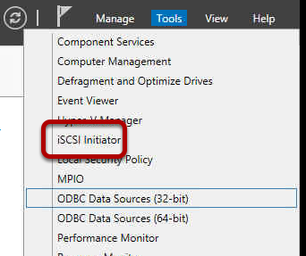
Now it is time to configure the iSCSI Initiator on the Hyper-V host
server. To do this, from Server Manager select Tools, then iSCSI
Initiator.

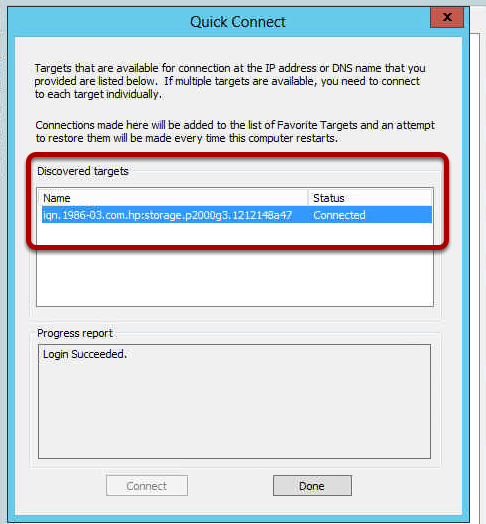
On the
Targets tab, enter in one of the IP addresses you assigned to the MSA 1040 NICs in
Configure HP MSA 1040 Storage Network section at the beginning of this blog post. In the example below, we used the first IP address of 192.168.9.7 and selected
Quick Connect. It will discover the iSCSI target and display it in the
Discovered Targets box and the status will state “Connected” (see image below).

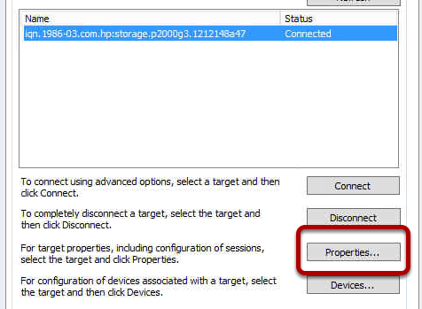
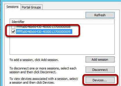
Once the target is discovered, select
Properties for
the connected iSCSI target. You will notice the image below. What are
we seeing here? Each Identifier represents a NIC or path on the MSA 1040
storage. Remember, in our configuration, we have 4 NIC’s on the HP MSA
1040 (2 on MSA controller A and 2 on MSA Controller B). You must add
each Identifier manually by selecting
Add Session.

Once you’ve selected
Add Session, you will be presented with the
Connect to Target screen below. Make sure you check the boxes below, especially the
Enable multi-path checkbox and select
Advanced.

In the
Advanced Settings, for the
Local adapter select
Microsoft iSCSI Initiator from the drop-down menu. For the
Initiator IP, select the Hyper-V Host 1 MSA Storage Team (
192.168.9.3 in this example). You configured this in the
Configure Hyper-V Host Storage Network section earlier in this blog post. For the Target portal IP, select the first IP address of the MSA 1040 storage (
192.168.9.7 in this example). You configured this in the
Configure HP MSA 1040 Storage Network section earlier in this blog post.
* You will need to do this for all 4 NICs/paths on each Hyper-V Host.

At this point you are pretty much done if you are OK with all the
default settings. However, if you choose to customize the configuration
each of the devices you just added above, select
Devices from the
iSCSI Initiator Properties screen (below).

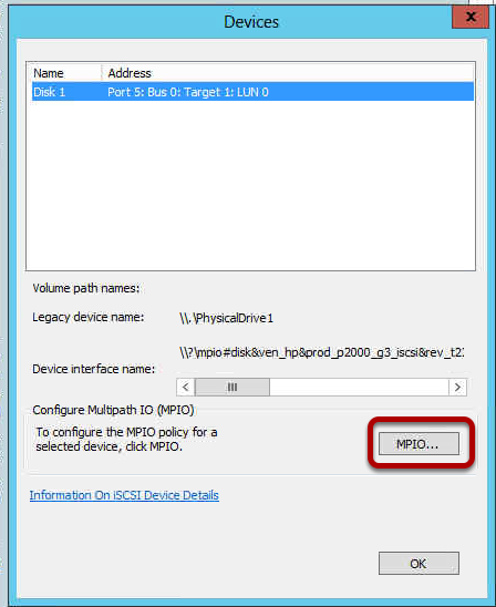
On the Devices screen, you will notice all the disks or LUNS
associated with the devices (sessions) you added. So what are we looking
at? Notice the
GREEN
highlighted areas in the image below for Disk 1 and Disk 2. Don’t worry
about LUN 0. Since our example included 4 NICs or paths on the MSA 1040
storage device, you will have 4 disks or LUNS for each device. In the
example below, you don’t see the 4
th device because you would
need to scroll down. So why are there two disks associated with each
device (Disk 1 and Disk 2)? The reason for this is because before we
configured MPIO and iSCSI on the Hyper-V host, we presented two
disks/LUNS from the MSA 1040 storage unit to the Hyper-V host server. We
presented a Quorum LUN and a Data LUN. This is not relative to the
iSCSI configuration but I thought it was important to understand what
you are viewing in the image below.

To configure the MPIO Policy for each disk/LUN, select the disk, then select
MPIO. You can configure the MPIO Policy several different ways. The default is
Round Robin With Subset. This is what we used in our configuration example.


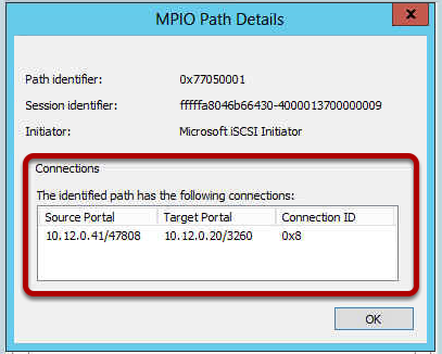
If you selected the
Details for each
Path ID, you’d notice that each one with have a different
Target Portal IP address (one for each NIC on the MSA 1040).